Thermography (Infrared Camera Application Technology)
High Performance Thermal Measurement and Stress Measurement with Thermography (Infrared Camera) Explanation (1)
In-page menu
Example of Stress Measurement
For a crane or other device used in the production process, stress measurement under an actual load may be required, since some cracks are observed at the stress concentration point. It is possible to measure stress remotely using an infrared camera with a telephoto lens without assembling scaffolding. For small parts such as MEMS, the stress is measured by microscope observation. Fig. 5 shows an example of remote stress measurement of a crane frame. The stress distribution chart shows that the stress concentration occurs at the corner portion R. Because of the thermal noise from measurement in the field and that lock-in signals to reduce the noise may not be extracted in many cases, a specific measurement is required. To prevent thermal noise, obstacles and shooting angle are carefully established so that reflected light does not enter the field of view of the camera. In addition, some software that extracts the lock-in signal from the temperature variation with the actual load is effective for use.

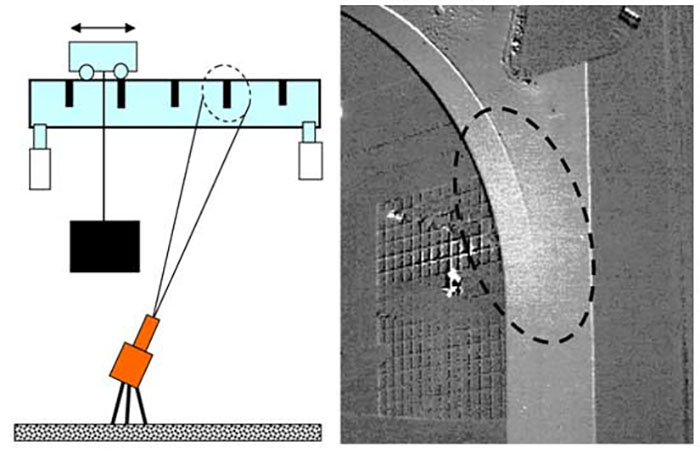
Fig. 6 shows a stress distribution chart of a four-point bending cyclic load test for a bone implant with a small, complicated shape. Although accurate strength measurement is required, since the implant is embedded in the body, it is difficult to measure with a strain gauge. Line segment 1 in Fig. 6 is the line through the stress concentration section of the screw hole, and the stress distribution is shown in Fig. 7.
-
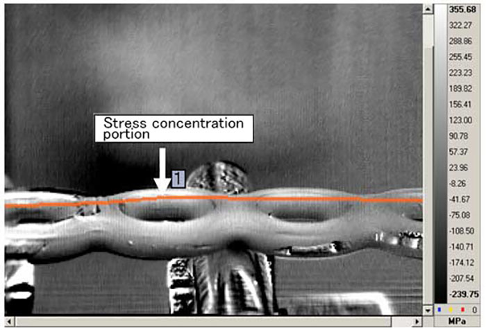
Fig. 6 Four-point bending stress distribution of bone implant -
Fig. 7 Stress concentration of bone implant (stress distribution of line segment 1 in Fig .5)
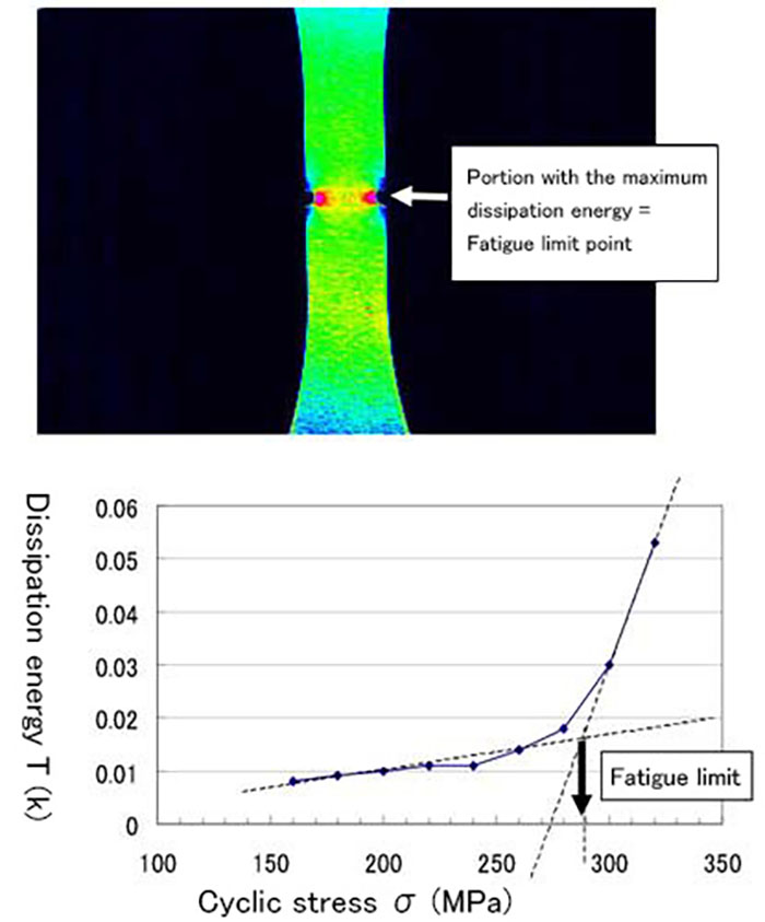
Fatigue Limit Measurement
The advantage of the fatigue limit measurement with an infrared camera is speed. While an ordinary measurement may take one to four weeks, the measurement can be made nondestructively within half a day. This technique offers the advantages of time and cost savings for screening in the development and design stages when examining different materials and shapes. Although the problems of ultra-long life fatigue (Gigahertz fatigue) from the inclusion of recent aged and high-speed equipment remain, time limitations make measurements with the ordinary method impossible. The infrared camera method is very effective since the technique measures the energy of the initial micro destruction. The camera can detect heat when the cyclic stress level is lower than the ordinary fatigue limit. Furthermore, since a portion of fatigue limit can be identified in a two-dimensional image, this method is useful in elucidating defects in shapes and weld beads. The principle of this method is deviation from Formula 1 of the thermal-elastic effect that has already been explained in stress measurement. By increasing cyclic stress, heat generation increases substantially from a certain stress level, and the micro fracture energy due to fatigue (= dissipation energy) increases. The folding point of the graph in which the cyclic energy and the fracture energy are plotted is the fatigue limit. (Fig. 8) As the load increases, it enters the plastic region, energy several times greater than the fatigue limit can be observed.